
NewsSheet
Exploits of our sister-group CREG, including
SnippetsLetters
Report of the May Field meet goings-on.Including
Doing the Ogof Draenen Grade 5 survey - Arthur Millet
An article about real, actual, surveying!
Speleogen - a Post-Processor for Survex - Mike McCombe
Software that mixes Survex's output with other data to produce DXF files for importing to Drawing & CAD software.
This year's conference will be happening just after this arrives on your doorstep. The CSG will be there with survey software to show off & give away, so please come and say hi so I can put names to faces.
As of this issue the newssheet that you used to get separately, telling of the exploits of our sister-group CREG has become incorporated into CP itself. We think this set-up makes more sense - please tell us if you disagree.
October 25th-27th will be the next field meet, where you can come and play with survey software, meet with fellow surveyors, do experiments on surveying gear, have nerdy discussions about data recording and processing and generally have a whole weekend of surveying, without having to actually survey anything at all!
It will be in Yorkshire, near Massam, with further details available from
E-mail: richardr@fcl.com
If your subscription is due for renewal you should find a form and a brief questionnaire enclosed. Postage costs have recently increased, and printing costs are likely to rise so, although we have managed to hold our prices down yet again, we cannot go on doing this forever. We do not receive any subsidy from the BCRA - the subject has arisen several times but Council have been adamant that the Special Interest Groups must be self-supporting. To help us plan for next year, we would like to know what you think we should be publishing. Please write (or complete the renewal questionnaire) and let us know whether you would prefer to see the page count increase as and when possible, or the price to remain down. If costs go up next year, it will have to be a choice between reducing the page count or putting the price up.
If this is not your own copy of Compass Points (perhaps it is the copy from your club library, or a friend's copy) then we would like to hear from you! We won't try to sell you a subscription, but we'd like to add your name to our database as part of our aim of free-exchange of information.
Now that Printed Papers may be sent sealed to overseas destinations we may be experimenting with other forms of packaging. Please let us know if you have any problems with your overseas copies.
As I explained in the last issue, we are planning to "float" the Cave Surveying Group as a separate organisation. This will be discussed at the CREG/CSG AGM, but I am not sure exactly when the flotation will take place.
There is a definite plan to move to centralised collection of subscriptions and, at some stage, this requires CREG/CSG members to pay a partial year's subscription in order to bring the renewal date into line with your BCRA subscription. As with the CSG flotation, I have not got around to thinking about the intricacies of this yet. In the meantime if you want to pay your CREG/CSG subs at the same time as your BCRA fees please let us know, or make it clear when your next BCRA renewal arrives; and I'll try to sort it out. If anyone wants to volunteer to be "membership secretary" that would be a great help.
Our 1996 AGM will be held at the BCRA Conference at Sheffield Hallam University on Saturday 14th September at 1:00pm. You will be able to gain admittance to the AGM without needing to buy a full conference ticket. UK members should find enclosed a leaflet informing you about the conference. Please notify David Gibson if you are thinking of attending the AGM; and a stamped, addressed envelope for a copy of the minutes.
Executive officers
CHAIRMAN Mike Bedford
SECRETARY David Gibson
TREASURER position vacant
Committee posts
Mike Bedford (Journal editor
David Gibson (Technical editor)
Wookey (Compass Points editor
Chris Trayner (Bibliographer & Digest
editor
Phil Ingham (President)
Richard Rushton (Meetings co-ordinator)
Nigel Lovell (without portfolio)
Andy Atkinson (CSG publicity)
· Cave Visualisation using VRML (Virtual Reality Markup Language)
· UIS proposed international survey symbol set.
Compass & Tape (The US Cave Surveying magazine) issue 40 arrived this month. Here is a summary of that and issue 39, held over from last month.
Letters: George Dasher comments on issue 38, arguing that trying to pick criteria for judging electronic cave maps is premature, that survey stations should be permanently marked at least every 10 stations, and that the criticised sketches in Mike Yocum's article were generally OK really - he's had to use much worse.
Bruce Zerr congratulates an interesting issue, and goes on to agree with Pete Sprouse's opinion that LRCFs are outdated and redundant. He describes his technique of draping the tape along a leg and then measuring perpendiculars from that to walls & features, now progressed to actually drafting the in-cave pictures properly to the same scale as the finished map, eliminating re-drawing and the need for LRCFs entirely. He uses dowels in the floor following the centreline for most stations, marking permanent stations with aluminium foil pulled out of a film can dispenser. He recommends steel carpenters tapes as they are easy to measure up to ceilings and 'over there' due to their stiffness. Finally he outlines a handy method for working out ceiling height without drawing or hard sums. You pendulum a torch so it shines straight up, and then measure the horizontal distance to the point at which your clino reads 100% or 50%, correcting for people's height and floor slope using another clino percentage if required.
NSS Cartographic Salon: Don Coons relates how he entered 6 surveys in the Salon - 1) Mertz cave, a 2.5 mile long horizontal system mapped in 1974, 2) A combined 'ink-blot' survey of all the systems in the mammoth area, 3) Sistema Cheve -20km & 1386m deep, 4) Buzzards Roost Cave survey, prepared for the Jury in the case arising from the death of a tourist on a trip here, showing the route from the visitor centre to the place where he got stuck and died, 5) Gua Lulit Siput, a 5.8km & 470m deep cave in Sarawak, and 6) Blunder Hole Cave 1600ft long and 408ft deep, plotted at 20 degrees tilt for clarity. All of these surveys were eliminated from the competition for reasons like 'entrances not shown' on the mammoth survey (this was for necessary political reasons), non-matching fonts on plan & elevation (because they were drawn by different people), line width too thick (on the surveys drawn up to be seen by Jurors across the room). He concluded that the judging criteria are rather too narrow.
Gearge Dasher replies, pointing out that the rules do at least somewhat standardise the judges decisions, which were previously entirely subjective. They have also improved standards. Not everyone can win, and when the standards are very high, even the tiniest flaws are enough to stop you getting an award. He recognises that there may well be room for change, and that continuous review of the rules is a good thing.
1995 surveying and cartography section meeting: A report of the annual meeting at the NSS conference with 28 members attending.
Cartographic Salon 1995: This gave the results of the 1995 salon which had 45 maps from 24 cartographers . The winning entry being Paxton Cave, Virginia, by Tom Spina.
Cave Cartography using AutoCAD: Bert Ashbrook describes how he enters the data direct into AutoCAD, which draws him the centreline, which can be examined in 3D before being drawn up as a 2D plan. He describes the limitation that there is no automatic way to redraw walls when the centreline they are drawn around moves due to later loops closures. He explains how layers are used to separate the different components of the drawing, so that it can be plotted at widely varying scales successfully. Walls are drawn as 'polylines' with layers corresponding to pen thicknesses, and AutoCAD takes care of dashing & dotting for you. Symbol libraries of rocks, mud etc. are very useful to save effort drawing floor details. Cross-sections are created from the finished plan to ensure matching size and features.
Documenting Cave Entrance Descriptions and Locations: George Dasher gives details on what to include when describing an entrance location, i.e. maps, description of what the hole looks like and its size, any other distinguishing features of the cave and approach. Bearings on useful objects (houses, mountain tops), photographs.
Report on the 'Criteria for Judging Electronic Maps' Session of the 1995 Convention - or Clueless in Blacksburg: Pat Kambesis describes how she was enlightened about electronic cave maps by actually having one demonstrated to her by Fred Wefer. She realised that they are not simply a picture done on the TV screen instead of paper, but a whole 3D thing with interactive elements. The session discussed electronic maps and decided that attempting to make rules was futile at this stage in their development, and programmers should be left to innovate in any way they saw fit.
Comments and Suggested Guidelines for Judging Electronic Maps: Fred Wefer, has been working in this area for more than a decade. He reminds us of his early definitions of the different cave map producing processes, resulting in four types of map:
Stage 1 - Data reduction by computer, plotting by hand, drafting by hand, final map viewed on paper.
Stage 2 - Data reduction by computer, plotting by printer, drafting by hand, final map viewed on paper.
Stage 3 - Data reduction by computer, plotting & drafting by computer, output by printer, final map viewed on paper.
Stage 4 - Data reduction by computer, plotting & drafting by computer, final map viewed on screen, and is interactive.
It is interactivity that makes the maps different, and requires new judging rules. The other 3 stages can all be treated the same - as the method of production is not of interest to the judges.
He remarks that the judges need to specify what they want shown, not how it should be shown, and goes on to give a provisional set of categories and items upon which judgement might be made.
Chairman's message: Comment on the renewed enthusiasm in the Survey & Cartography section after a noticeable lull.
Letters: George Veni adds his comments to the Cartographic Salon judging debate, believing that the current system actually works quite well, and that as they are judging Maps, not Surveys, the difficulty of collecting the data must be considered irrelevant.
Bill Mixon comments that when judging electronic maps it is important to consider the real utility of features, not just how 'whizz-bang' they look.
Blunder Location: The Larry Fish article published in CP 9
Accuracy of GPS receivers and an Attempt at do-it-yourself differential GPS: The Bob Thrun article published in CP 12
Why have lava tube survey standards / Kazamura Cave Project of the HSS: Kevin Allred explains why they needed a set of standards for the survey of this big cave on Hawaii, finding the old standard of not bothering with clino readings to be inadequate. He then describes the rules they produced, such as 'Survey everything that you can get though with your helmet on'. Most of the instruction are what you would expect but there are a few specifics and subtleties. Lava is often significantly magnetic so backsights are recommended and it is suggested that you keep your compass away from the rock! Due to the extreme consistency along the length of some passage sections all leads have to be marked with tape.
Cartographers Corner: Pat Kambesis talks about effective use of line width variation, showing a couple of examples. One is Carol Vesely's survey of Du San Dong (China), which shows an impressive level of detail on the Elevation, as well as the plan. This makes a much more interesting elevation than is typical. The other is a computer-drawn isometric view of Monolith Rift. This is a nice map using some interesting techniques to give a good 3D 'feel' to it.
Survex version 0.70 should be on the net, just about when this hits your doorstep, although the documentation remains somewhat behind the reality. It will also be available at Hidden Earth 96, and the docs may even be up to date by then. Come by the CSG stand if you want one.
There has also been a new release of WinKarst since CP12, but I've run out of space & time again, so you'll have to wait to get the low-down on that one.
Dear fellow cave surveyors and program designers, there is yet another reason not to miss the 12th International Congress of Speleology in La Chaux-de-Fonds, Switzerland (August 10th - 17th, 1997).
We will organise meetings and post-congress workshops covering diverse aspects of cave surveying, mapping, and archiving. The main theme will be the evolution from cave cartography to integrated speleological information systems. I would like to invite you to present your work in the sessions on 'Cave mapping and archiving', display your maps in the map exposition, or to participate in one of the two post-congress workshops on 'Map Design' and 'Computer Aided Cave Cartography'. There are so many sessions during the conference that I would like to highlight one meeting of special interest to programmers:
Meeting on 'Computers in Speleology' with presentations, demonstrations, discussions, and practical exercises.
The main goal of this day is to inform cavers about existing software in all areas of speleology. The meeting will also bring together many program designers for exchanging concepts and ideas and for planning joint projects.
One round table discussion will focus on various applications of computers in speleology, another will compare the different approaches to cave survey data processing. We invite cavers to demonstrate their use of programs, and programmers to present their projects or give hands-on tutorials of their software.
As one of the talks, a multimedia presentation of the Toporobot method will be given. The demonstration will illustrate the concepts of geographic information systems as applied to modelling and visualisation of karst phenomena. Such systems integrate different types of information relating to caves (geographic, historic, bibliographic, structural). There will also be a meeting of the 'Toporobot Users Group' which will allow interested cavers to learn the basics or the subtleties of this program.
After the conference, a 3 day workshop will allow programmers to continue their discussions. It will be held at the GIS-Lab of the Department of Geography, University of Zurich (August 18th - 20th). This workshop is especially aimed at authors of computer programs for cave surveying and mapping. It is targeted for 25 persons.
The five central themes are:
On the third day, we will be joined by the participants of a workshop for cave map designers, who will relate the practical aspects of using different programs for calculation and representation. This will permit us to better define the present and future needs of program users. Together, we should define the methods and concepts best adapted to underground cartography.
Discussions will help to understand each others concepts and notations for speleometry and speleography, and hopefully to find an unified approach. This would greatly facilitate designing a common format for data exchange. Such efforts have failed so far because it was difficult to reach a consensus about a format, when the underlying concepts where unfamiliar or too divergent. The main goal of this event will be to lay the groundwork for future co-operation.
Contact person:
Phone: ++41 1 257 51 52
E-mail: heller@geo.unizh.ch
The detailed program of the international congress will soon be on the conference www-server: http://www.unine.ch/UIS97/
This email group has generally been quiet, but a discussion on the pros & cons of LRUD recording broke out in May/June from which I intend to publish some of the postings here.
Wookey
The Cave Surveying Group (in conjunction with the Cave Radio & Electronics Group) held a field meet in the Peak District on the weekend 18th-19th May 1996.
The meet was well-attended overall, although most of those present were 'Cave Radio' people rather than 'Surveyors'. The Friday night was exceptionally cold, getting down to just about freezing. I arrived at about 1am and couldn't be bothered putting up a tent, but I had forgotten my karrimat so I had an extremely chilly night in my van - joy! This prompted a very early rise at about 7.30am.
Full cooked brekky was provided and duly eaten. The Cave radio mob collected all their bizarre gear together and set off to Stoney Middleton and Carlswalk Cavern.
Team surveyor, which at this point consisted of Wookey and Andy Atkinson unloaded a small pile of computers, instruments and surveys and got down to business.
The areas of discussion for the first day were:
We have generated an interest in this as our (Cambridge University Caving Club) cave in Austria has got bigger and bigger, and the practicalities of producing a new plan & elevation of 15km of cave in a year have got out of hand. The drawing itself takes ages, but the sticking on of labels, drawing of grid, adding of cross-sections etc. is just as time-consuming, and would be much easier on some kind of CAD/drawing system, if only because at least things would be horizontal when they should be.
Actually drawing on the computer is difficult though, so we are currently looking at creating film originals of each section of cave, then importing them into the computer to be stuck together, labelled & annotated before printing.
The pictures can either be scanned or traced on a graphics tablet. We only have access to a scanner so we opted to test out the limitation of this process first. A sizeable section of Kaninchenhöhle, comprising about 15 surveys had previously been drawn onto paper (as extended elevations), then traced onto final film version. A 5cm N-S/E-W cross included for orientation and scaling of the final sketch, and X's used to mark the stations at the 'joins' of different sections. These had been scanned in before the weekend.
We used a couple of different vectorising packages to turn the large bitmaps into vector images again. This worked OK, but many of the lines became broken, and all small detail (e.g. traverse 'T's and the crosses we put on for lining up the plots) was poorly reproduced. [I have since found that scanning at higher resolution to give about 8pixels across a typical line width will give massively improved results] We found that the effects were much the same with both Adobe Streamline and CorelTrace, suggesting that it was an algorithmic problem rather than one of poorly written software.
It would be interesting to see how much better the results are with a graphics tablet and 'manual' vectorising. Anyone got one we can borrow?
Having got the pictures into the computer there were a number of other issues to consider. We wanted to be able to manipulate each 'cave section' independently of the others, so that sections can be moved around to line them up. This is easy to start with, but as soon at the section is ungrouped, in order to change any lines within it, then it becomes impossible to regroup if there are any overlying cave sections (which there inevitably are). This problem could be got around by putting different cave sections on different layers.
The other thing that we need is to be able to select which elements will be printed. This is primarily a scale issue. For a small plot then some of the detail is not needed as it will be illegible and clutter up the plot. Also the size of labels needs to change for printing at different scales. As the plot gets smaller then the labels need to be relatively larger otherwise they become illegible. These requirements are also best met by the labels, walls and details being on separate layers so that we can choose which to print.
Unfortunately normal 2D drawing packages do not really allow the above. If you put parts of an object on different layers, then the act of grouping things on those multiple layers moves them all to the same layer. It is necessary to group the different aspects of a cave section (walls, detail, labels) so that when it is moved they all move together.
This led us to determine that only CAD systems could really do what we wanted, although a workaround for the drawing packages would be to do all the fine editing of cave sections in a separate file in multiple sections, and then only assemble them for a final plot. We will be trying out this technique and reporting back on how it works.
Whilst working out what was required we tried to specify a set of layers for all the possible uses we could think of for the survey. i.e. this is looking at layers for use a way of selectively including things to appear on the final plot. This is the list we produced. The things grouped together on the same layer are things that we expect to always want to plot together. You could give absolutely everything a separate layer, but this would make changing your plots settings more fiddly, and keeping track of the whole thing somewhat harder.
Layer Definition for CUCC surveys - Wookey & Andy Atkinson 1996.05.18
SpeleoGraphics. This is a package from Germany. It has a proper Windows install program, and seems at home on both Windows 3.x and 95, with an English menus option. The viewer looks pretty but doesn't really seem to be easy to use or fast, or actually provide any useful facilities (apart from having a grid). We did not try processing anything other than the data that comes as an example. That seemed fine. Overall we didn't think that it was worth the 40DM asked (£17).
Compass for Windows. This is the second or third WinCompass release and it is beginning to look pretty sexy. We didn't fully experiment with the functionality, but it has certainly improved since the review in Compass Points a couple of years ago, with the wrinkles generally ironed out, and loads of new things put in.
Karst for Windows. This release of Karst is also pretty competent with a great deal of functionality - opening multiple surveys, editing multiple surveys, having the loops shown up in different colours, as well as various nice features retained from the original Karst for DOS, such as the simultaneous elevation and plan views. The thing that lets it down is that it seems to still be pretty flaky. We didn't have to fiddle for long before it fell over with a GPF.
This was some practical work based on Andy Atkinson's article in CP10 describing some adjustments required to typical LRUD info to make it useful for computer processing for 3D visualisation. We took a sample set of data (One primarily vertical route in Kaninchenhöhle - 'France') and retro-fitted the new-style LRUDE data according to the rules we had formulated. This exercise showed us that it is a laborious job, taking a about an hour a survey (say 15-20 legs each), as it requires much peering at sketches to work out what the answers the original surveyors never wrote down were. It is noticeably harder for pitch series than nice horizontal passage (where people tend to take more/better LRUD info anyway).
We also found a limitation of the existing method, when the survey goes from begin basically horizontal, to up a pitch. No distance is recorded for how far back/from the station the back edge of the pitch is, only the other edge, so the visualisation software would have to make it up. The best way round this seemed to be to put in both LRUD and NSEW readings at such stations.
As the software to actually view the results of this exercise wasn't written then we couldn't reach any final conclusions about how well it worked! Work has been ongoing on this over the summer and we may just manage something to show at conference.
On Saturday evening Pete Grant and Terry Whitaker turned up, doubling the number of surveyors! The evening consisted of being royally fed by the CREG 'Soup Dragons' (Rosy Rabson & friend), then trundling off to a cosy pub to drink beer and 'engage in much fruitful discussion'. On Sunday, after breakfast, the CREG cleared off , leaving us it peace with our computers.
We looked at the then brand new Survex v0.69a primarily examining the relevant of features to Pete Grant's work on Easegill. The recently added diving data functionality was immediately recognised as important, and indeed the very next weekend John Cordingly fished out a great pile of data from his loft, for Pete to enter. The other new features were detailed in the last issue of CP, so I won't cover them again here.
We looked at the Easegill dataset, and discussed the difficulties of this sort of large mapping project, with many people involved. Everyone takes their notes differently, and some of the older surveys especially are of dubious quality. Pete is working on using the BCRA Grade files provided, as well as more detailed specifications of accuracy within survex to help give priority to the better surveys. Another useful feature here is *close, which lets you process some surveys, then fix everything exactly where it is before adding more surveys. This prevents the later loops from having any effect on the earlier ones. It is particularly useful for drawing up new stuff on an old survey.
To get anything more realistic than the sort of square , rectangular & cylindrical models that are commonly produced from LRUD data, you need to include more information about the shape of the passage, and then just use the LRUD info to position the shape around the centreline. We looked at a scheme where you simply give each leg a 'passage shape' shape number, specifying that it is canyon, rift, phreas, bedding plane, square, etc.
The difficult cases are keyhole passage and hading rifts. A keyhole is really the superposition of a phreas and a canyon, and it needs more than four numbers to draw it (you need to know where the top, left, right & bottom are, and you need to know where the top of the canyon section is, and how wide it is. 6 numbers. The neatest solution to this is to allow superposition of section shapes so that a keyhole is done as a phreas and a canyon on top of each other, although this immediately changes the scheme from being a simple 'shape-number for each leg'. Hading rifts also require an extra piece of information in their angle. We also argued about how these numbers should actually be given. Should the angle of a rift be specified down from vertical or up from horizontal? Up from horizontal seems more natural, but you also need to know which way it is leaning over, otherwise it will be back to front. Also in rifts which hade around about 45 degrees people find it difficult to choose what to write down for LRUD info - where is the roof? The only meaningful solution to this is to give the outside dimensions, i.e. those which enclose the cross-section completely.
We then wondered how easy it is to cater for less general shapes, so that you get the little 'ears' on a bedding-developed phreas, and other less simple passage shapes are properly represented. Andy A suggested that we use two numbers - one for the basic shape - i.e. the way the LRUD info controlled the positioning, and another for the detail shape (chamfered corners, pentangle passage etc.). Eventually a method was finalised that didn't seem over-complicated, or have horrible special case, but did cover most passage shapes. That will be the subject of an article from Andy at some point, so I won't give the details here.
So it was an interesting and productive meeting, despite not getting round to our intended practical experiments. I hope to see a few more of you at the next one in October.
Arthur Millet
This article is something of a departure for Compass Points. It is the first thing we have published that describes actual surveying, as opposed to instruments or software. It also came on real paper written with a real pen - hardly a floppy disk or net connection in sight!
Arthur gives a detailed description of the mammoth task of surveying Ogof Draenen, including the grimness of one trip, and the often forgotten difficulties of actually getting all that data drawn up.
Ogof Draenen had been a long term dig on Gilwern Hill being dug by Morgannwg Caving Club members when word came through the grapevine that it had gone big.
On the 21st Oct 1994 a Chelsea Spelæological Society trip was hastily organised after abandoning the intended diving trip into Agen Allwedd, due to the inclement weather. John Stevens, Mike & Helen Green, Geof Newton, Gary Jones, Stuart France, Amy Marchant and myself headed off for the infamous pirate trip into the new system (CSS N/L Vol. 36 No. 7). We were not to be disappointed and all had a superb trip down the streamway to what we later found out was Rifleman's Chamber.
During the trip, and afterwards, several of us started talking about the possibility of surveying this fine cave, whilst also looking at getting permanent access for C.S.S. members in the process.
Due to work commitments Dave Ramsey declined to do ant of the drawing up but would help out on occasional weekends doing the book. J.S. & myself were going to do the bulk of the book work in the cave, while John could not do any drawing up until after Easter 95, but in his limited spare time up to Easter would try to produce something for White Walls [The C.S.S. hut - Ed].
During the next couple of weeks out plans started to take shape and initial discussions with M.C.C. were very welcoming. A trip to Cardiff to meet M.C.C. members at their mid week meeting, also included the first slide show on Ogof Draenen.
A few parameters were outlined by me on how we, C.S.S., would expect M.C.C. to deal with the data emphasising the need to return drawn up data/drawing promptly and regularly. The duty lay with Andy Kendall & Rhianon Hicks who had volunteered to do the drawing up of our data. I also pointed out to all concerned that the amount of paperwork associated with our survey work would be very considerable.
By now the round trip had been discovered. We now had 20km in front of us, and while this would be a priority to establish a framework to hang the rest of Draenen on , we, the surveyors, would require a free hand in arranging trips. This was because of the vagaries of numbers wishing to survey while having the ability and freedom to move to where any new breakthroughs may occur. All of our surveying trips would be on Saturdays and any M.C.C. members who wished to help were given on open invitation, either telephone me or turn up on a Saturday morning.
On the w/e of 19th Nov 1994 the grade 5 surveying began with John Cooper & Mike Green starting at the entrance working in, while John S, Helen Green and myself started at the cairn junction working out. We met up at the bottom of the waterfall at my station No. 18 being Mike's No. 35. As there was still plenty of time left in the day we moved off into the cave, Mike and John C. going upstream from cairn junction to the bottom of big bang pitch. John S, Helen and myself doing downstream. The day ended when the number of main bulbs blown (5) exceeded the spares which left us with 3 lights between us going out.
Our first hiccup occurred early, while J.S. was calibrating the compass at Pwll Ddu, with the realisation that his helmet had a steel band around the rim. The offending rim was removed, the dubious readings of the earlier trip re-done, but the most far reaching question was over work done in previous years, on other C.S.S. surveying trips when he was reading the instruments.
Over the remaining weeks the surveying progressed downstream to the Cascades (26/11/94), along White Arch (26/11), Indiana Highway (3/12), Megadrive (3/12), Perseverance II - Players Tunnel to St Davids (10/12), Squirrel Rifts ()17/12 & 29/12), Haggis Basher & Farr Agent Blorenge (14/1/95), to where the day's surveying stopped at the Chocolate Blorenge Junction.
Meanwhile Gilwern Passage was started (31/12/94 & 7/1/95), and the Entrance series passages (19/11/94, 10/12/94, & 15/4/95).
Attention then turned to Beyond a Choke Streamway (4/2/95) from the Cascades to I.B.C., then (11/2/95) when we experienced our second hiccup. J.C., J.S., and myself had no problem at first but due to the fact the we were all wearing dry gear/furry suits, the wet, cold conditions started to tell, principally my endeavours with the pencil.
A rest and food at the days 21st station partly warmed us up before continuing ever onward. The level of water was rising but we did not really notice it. However by the time that the Narrows was reached I found co-ordinating my shaking left hand to the book held in my right hand an extreme mental effort. While J.S. & J.C. watched their stations submerge I was chest deep in flowing water, trying vainly to maintain standards, and looking on the mud-encrusted walls for anything noticeable to end the day's trip with a permanent marker. Ahead I found one, albeit whilst standing waist-deep in running water, and we called it a day.
Going out was as entertaining as any other passage being traversed in a flood pulse can be. When we reached the surface the sun had gone down but the snow that had been so abundant this morning was now gone.
A rethink on the surveying ensured that we were now to abandon the streamway/round trip until the spring/summer, and move on to the abundant dry passage. At about this time Nig Rogers, S.W.C..C. and friends put in an appearance providing us with extra information about passages not yet visited by us.
Siambre Ddu passage (18/2/95) with its close proximity to the old balance shaft quarry was next to enter the nook. The w/e 25/2/95 saw the start of surveying along Canyon West passage, continued on 4/3/95, then Canyon East (11/3/95), and end passages with Tractor Tracks (8/4/95), leaving only Big Mole and bits at the start for later.
The first section profile of the grade 5 was printed by J.S. in mid January 95 on a limited edition of 2 and not until the April C.S.S. Newsletter Vol. 37 No. 4, did the compilation section of the C.S.S. G5 and the M.C.C. G2 come into the public domain. We were now getting a feel for the place enabling us to correctly correlate individual passages to one another, however despite a near 10 kilometres in the book there were huge gaps with a long way to go.
On the evening 12 March Stuart France produced the Grade 2 of the extensions in Gilwern Passage going north underneath Illtydian's Chamber, found by Nig and friends two weeks earlier and named Galeria Garimperios. The large passage at the start, Forever Changed, is 200mts to the first stream inlet junction. Left is I Gwter Fawr, the mud duck, dye tested to the Cwm Dyer Valley by the Lime Kilns, and since explored for about 1.5km. Straight on upstream in the inlet Hearts of Oldham Glory/Echo Inlet. A small passage at the second junction takes one via some very pretty passage to Indigo Rift, a Tall major fault on a heading 70/250°. We, M & H Green, J.S. & myself made a start on the 18th March and over the next few weekends (25/3, ¼ & 8/4) with others, except for Y Gwter Fawr for which we were waiting for a drought, thought we had finished this area.
Weather permitting our attention then turned towards completion of the round trip so on the 14th April 95 J.S., J.C., A Tharratt and myself set off for Agent Blorenge. Following the collapse of my compass after the trip of 14th January in Far Agent Blorenge, A.T and I resurveyed all my previous stations. This was made easier by our policy of using Walls/large boulders as normal stations and leaving a small mark at each one, with numbers on junctions and intermediate stations where required. Once we had completed the resurveying we caught up with the others just after the second sewer where we joined up into one team. The day ended about 90 metres short of the confluence with Beyond a Choke Streamway.
A major talking point among the surveying team was the Grade 5 survey, "where is it?", and "have you seen it?". Well, john and I had met with Andy & Rhianon on a couple of occasions to sort out our note book interpretations, and had been in touch over the phone and post. We sorted through the entrance series, Upstream/Pen-y-Galchen Passage, Gilwern Passage. John sorted out a few thing in white arch, Indiana Highway & Mega Drive. Line diagrams of Canyon Passage together with pages of calibrations arrived, then nothing. Phone calls to Cardiff proved elusive, 'everything's coming along fine' was the standard reply. Rumours started circulating about the amount of paperwork arriving through the letter boxes in Cardiff, and with the towel being thrown into the ring by Andy & Rhianon. At this point John realised that he was going to have to take over the Grade 5 drawing in order to have something for White Walls and the B.C.R.A conference in September. Easter had come and gone, then May, and it was into June before John started to do a bit of drawing. Firstly from the Pioneers extensions, so at long last we the surveyors were getting turnaround on our books and any problems could be ironed out quickly.
Meanwhile back in Ogof Draenen, Nig & friends were having a little dig at the end of Elliptic passage that went big into ancient fossil passage he named 'Gone with the Wind' and 'Gone in the Years'. The Weekend 29th April saw two teams into the new extensions being only the second party to visit. One of our eccentricities in our surveying has been no reconnaissance of passages prior to drawing them up, excepting the pirate trip and round trips in Squirrel & Far Agent Blorenge. This means that apart from glancing at the Grade 2 we are always going somewhere new, making the joining of a survey trip usually interesting.
For those that weren't there, a rather nice-looking, if not quite finished, plot of the Survey was on display at the conference, and the above effort was recognised when this project gained C.S.S. the Arthur Butcher surveying award.
Mike McCombe
The power of Survex in being able to take files of cave survey measurements in a friendly format and perform the mathematics to turn it into a line survey must be well known to any CP reader. What struck me when I first began to use it, however, was a big gap between its output and a fully finished high-grade cave survey complete with all the passage details and pretty lettering. Although there seemed to be steps towards automating the drawing process further, as witnessed by discussions in CP on the handling of LRUD data, the prospect of being able to completely automate the creation of something as attractive as a good hand drawn cave survey still seemed a long way off. On the other hand, graphic design and CAD software for the home computer are now good enough to allow even someone as artistically challenged as myself to produce respectable diagrams. It thus seemed to me that the best approach would be to be able to transfer my Survex output data into a graphics design package, without losing any of the precision. This could then be used as skeleton around which the finished drawing can be produced.
Very little thought led me to the conclusion that the tool I needed would post-process Survex's .3D file into AutoCAD DXF format because this seemed to be the most widely supported 'standard' Olly had actually already developed something to do this (3DTODXF) but had not taken it as far as I wanted to go, so I sat down with a pile of manuals and wrote my own. Unlike Olly, I'm unable to produce platform independent 'C' so I stuck to what I know and wrote in a C++ dialect, specifically for Windows 3.x
The initial objectives were to be able to create a standard drawing file containing separate layers for
The first problem encountered when trying to apply Left/Right/Up/Down is that "left" and "right" have to be interpreted relative to some specific direction. Although there are various different conventions on this, I chose to assume that "left" and "right" are perpendicular to the leg from the previous station, facing in the direction of progression along the passage. There are a couple of special cases which need to be handled:-
The other tricky issue with LRUD data is how to handle junctions. With current surveying practice, the simple answer to this question is "don't" ! There just isn't enough information available to the program to allow it to join the passage ends correctly. However, as my objective was only to provide construction lines to be used with the surveyor's sketches in making the finished article, leaving the ends open at junctions isn't too serious.
In some cases, such as when surveying around the edge of a large chamber, either "left" or "right" values may be missing. This doesn't cause much of a problem as the left and right wall lines are built up separately and any missing points are just ignored.
To use all this, the LRUD data is first separated from the original Survex input files using a text editor and ordered according to the direction of progression along the passage. Occasionally, if a passage has been surveyed from opposite ends, for example, it is necessary to swap "left" and "right" values but generally the production of this file is pretty painless.
As I was fortunate enough to have access to a commercial terrain database of the UK it seemed useful to be able to add the surface, as another layer, to the drawing and to be able to annotate each station with its depth beneath the surface. A simple terrain file format was arrived at which specifies the height of each point in a grid. Rather than just use these points 'raw' to create the terrain view, it was decided to use the terrain file as a mini-database and to allow the user to specify the size, position and resolution of the 'mesh' which is then calculated from it. Originally, simple linear interpolation was used to calculate the height at any point within a terrain 'tile'. As this build the terrain out of flat 'tiles', a slightly better effect is obtained by increasing the order of interpolation to a cubic function fitted to more of the surrounding data points. Each 'tile' is then curved in accordance with the general shape of the hillside.
Overall, the results of this seemed quite satisfying but the usefulness of this feature to the general user is somewhat limited by the unavailability of data at an affordable price. Alas the licence restrictions on the data that I have do not permit me to pass it on !
Following on from Peter Eland's article in CP 11, it ought to be reasonably possible to create a SpeleoGen terrain file at, say, 100m spacing by hand from a 1:25,000 or 1:10,000 map. Using Survex, the only way to reduce the rather jagged appearance of the straight-line mesh is painstakingly to digitise more points. I suspect that as the 'spatial bandwidth' of much caving terrain (and certainly contours on maps) is no more than a few 'undulations per kilometre', sampling at 100m spacing ought to capture almost all of the features but, in its raw form, may not look very good. SpeleoGen's use of surface interpolation allows one to produce a finished picture at a closer line spacing than the original data, in this case 50m or 10m line spacing and is analogous to the 'spatial filtering' techniques used in radar imaging.
The very first version of SpeleoGen was purely a data processing program: it read the 3d file and created something which could be loaded into a graphics package. Given my objectives, there was no real need for the program itself to display anything as the graphics package would always be able to do this. However, as the output DXF files got larger, having to load the output into AutoCAD or Designer to 'have a look' became more and more inconvenient. Finally, I succumbed to pressure to show the selected 'view' on the display and to be able to pan and zoom it at will. I also added the ability to find stations in the display by name and to select the centre point using the mouse.
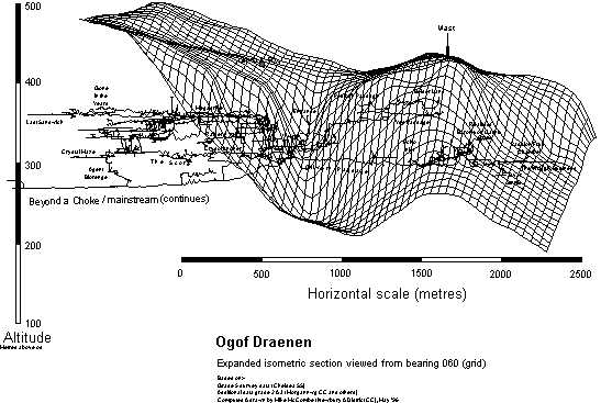
From the earliest stages, SpeleoGen was used to post-process Survex output for Chelsea's grade 5 survey of Ogof Draenen, As John will relate in the next part of his article, the DXF output from SpeleoGen is loaded into MicroGrafx Designer which he uses to create the finished product. Many of you will have seen the results.
A rather different view of Ogof Draenen, drawn by me is shown below, again using Designer as the drawing package. The DXF produced seems to work well with everything tried (except CorelDraw). It even successfully translated into VRML to produce a 'virtual reality' cave survey !
I would be very happy to make SpeleoGen freely available to anyone who would like a copy. Just send me a 3½" diskette and an SAE to Mike McCombe, Kingswood House, Saxon's Acre, Brightwalton, Newbury, Berkshire RG20 7BD. Likewise, anyone with an interest in the source code for a nonprofit making use is welcome to it. Perhaps by the time this appears in print I may have uploaded it to the UK FTP archive.