Psion stuff
Last updated: 2002.10.28
This is not a trivial excercise, so unless you like this sort of
thing you should at least wait until your guarantee has expired.
Don't blame me if it all goes horribly wrong, but the following
worked fine for me.
Thanks to Vipin Sachdev (reader of a Psion list who found
this page useful) and an engineer called Lawrence for the pics of a
dissasembled Psion5 on this page.
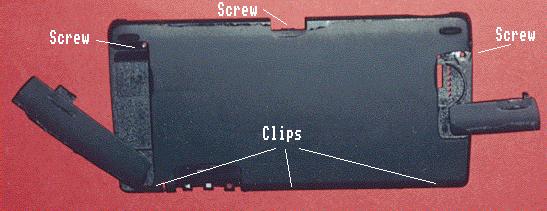
The base is removed by undoing 3 screws: one at the bottom of the
battery compartment by the catch (you need to lift the lid), one
under the flash card lid where the pen goes (you need to take the
pen out), and one under the right hand side of the little 'void if
removed' label inside the backup battery lid. The bottom then comes
loose.
To get it off, slide the keyboard forward and then lift the
rear of the case whilst pushing it in the direction the keyboard
opens. This releases the three clips just under the keyboard (the
middle one is next to the little hole for the 'open/closed'
microswitch). This is fiddly as the one at the PC-card door end is
tight - an internal vane on the case pushes against a capacitor
when you try to release the clip. There is no clearance, and
judicious use of just the right level of force is needed.
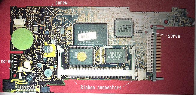
The PCB is held on with 3 screws (obvious), but you can't get it
out without removing the rear section of the case (the battery
terminals hold it in). To get this off you need to close the
battery door then lift the top of the rear piece halfway along
(about 1mm) to release the clip there.
Now everything is exposed and you just need to release the ribbon
holders (slide the 2 ears towards the ribbon entry and the ribbons
become loose), There is one for the battery negative/speaker, and 3
for the display/keyboard/touchscreen - one on top and two underneath.
Now you can remove the PCB, leaving the chassis, screen and keyboard.
Next, remove 2 pins in keyboard/screen hinge. To separate the 2 components
then slide keyboard forward on rails until it slips off the end.

The screen is separated from the casing by sliding it down. Pull on the
inner half of the hinge bulge to get purchase. It's quite stiff but careful
levering on the hinge bulges will ease it out. Once it is about 7mm free it
comes out quite easily.
I couldn't see how to seprate the hinge spring wire from the screen casing
in a reversible fashion so I just left it attached. It's not really a
problem.
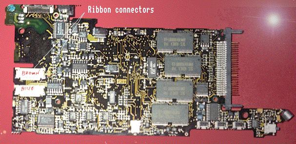
Now you can get at the screen flexribbon, which is the bit that usually
breaks in my and sachdev's experience. Replacement cables can be obtained from POS Ltd, who are also supporters of
the psilinux project. They are not particulalry cheap at GBP 25, but so far as I know you can't get them anywhere else.
Here are some more pictures of the
various parts, and the device disassembled into major components: keyboard,
screen, case, PCB, chassis. These were taken by Lawrence, the Indian engineer
who did just that to fix Vipin Sachdev's broken screen cable (It seems that
this cable is prone to wear in tropical countries).
I have connected my Garmin GPS12XL to my Psion5 for use with
palmtop bv's route-planning software and for cave location in
Austria. It's not trivial to get this all working if you are making
your own cable, so I've documented what worked for me.
The psion connector can be bought from CPC
Plc. part number:CN00843, described as 'PCMCIA Cable assembly'.
£8.95+VAT = £10.52 (The keying is not identical to the
psion-supplied part but it fits properly).
The Garmin connector is best bought from the pfranc
network which is a rather odd 'hardshareware' concept. You buy
the connectors from your local franchise and pay whatever you think
is 'reasonable' - a couple of quid seems fair.
If you also want to connect up the psion power you need the connector:
This is a 1.3mm internal diamter barrel plug, also available from CPC Plc: part no. AR70628 (bent) or AR70624 (straight). If the supply is >6V (eg a vehicle) then you will also need a regulator (see the discussion below).
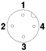
Connector pinouts
The hard bit is knowing which pins in the Psion and GPS connectors
are which.
The Psion connector is numbered like this (looking into the cable):

And here's a pic looking at the top of the psion connector (kindly supplied by Ian Bradshaw)
For the GPS connector I have numbered the pins like this
(looking into the cable):
Wiring the cable
You only need 3 wires: RX, TX and GND.
They should be connected up like this:
Garmin connector:    Psion connector:  (9pinD)
  1 ------ TX -----------  4              3
  2 ------ GND ----------  15             5
  3 ------ RX -----------  8              2
  4        Power
If you use the CPC connector, then you can wire it up by colour. In Feb 2000 (just in case they change them sometime) these were:
Garmin
  1 ------Blue          (TX, pin 4)
  2 ------White         (GND, pin 15)
  3 ------Yellow/Black  (RX, pin 8)
For using the system in a car you really want a multi-headed
cable that supplies power to the GPS and Psion too. You can make one
amazing 4- or 5-headed thing (12V power, psion 6V power, GPS connector,
psion serial, computer serial), but I've found it sensible to split the
functionality in two or three leads: a 3-headed GPS lead (GPS, power
connector, serial connector), and then have adaptors for the appriate
power or serial connections (eg: serial connector<->psion serial).
Exactly what is best for you depends on how many ways you use your kit.
Do you want to power the psion from the car without the GPS present? Do
you want to power the GPS from an external battery as well as the car? Do
you want to have the GPS and psion serially connected just using internal
batteries? How may different leads are you prepared to make/buy? Do you
need to carry all this crap up mountains and thus want to minimise weight
but maximise versatility and robustness?
A psion <- power -> GPS -> Psion cable is wired like this:
Psion power    vehicle/battery    Garmin       Psion serial    (9pinD)
 connector     power connector   connector      connector
                                    1 ----- TX ----  4              3
 Outer ----|------ V (GND) -------- 2 ----- GND ---- 15             5
          _|                        3 ----- RX ----- 8              2
 Inner --|  |--- +V (Power) ---|>-- 4
         |__|                 diode
    6V >0.3A regulator
In practice the garmin connector does not have room for two cables
coming out of it so it is best to use whichever connector has most
space to do the 'Y' splits. I used the power connector. If you add a
9 or 25-pin D as well (so the same lead can be used for connecting
GPS, psion and computer (but not all three at once - the serial
ports would argue)) then that might be a good place for the split.
Note that the position of the diode is significant. If you put it
in the GND lead instead of the POWER lead then (depending exactly
how things are connected up) the serial connection may not work as
the serial signals will not tolerate the diode in the ground
reference.
If you want to power your psion from the car or a >6V battery, then
you need a regulator to give it the 6V it expects. A simple analysis
suggests that as the psion+backlight+serial port draws no more than 160mA
a 200mA regulator should suffice. You can get one of these (ZR78L06C) in a
transistor package (TO-92) small enough to fit (with care) inside the
bent psion power connector, described in parts,
above. However I found that whilst this worked fine for non-backlit use,
after 20 mins with the backlight on it got unreasonably hot and shutdown.
It would work again once it cooled but this obviously isn't very
satisfactory and the poor thing didn't last long treated like this (and melted the connector). A bit of thought shows that with the vehicle supplying
14.5V when running, and the Psion5 consuming 160mA at 6V the regulator has to
dissipate 1.4W, which is too much for such a small package in an enclosed
space. The next regulator is the (L7806CV) which is a larger TO-220 package
but will take up to 1.5A, and is still only 70p. The disadvantage is that you
can't hide it in the power plug, although you might be able to get it inside
a car cigarette-lighter socket - I haven't tried.
Wiring a PC<->Psion serial cable
This is the spec for a standard (as supplied by Psion) serial
cable, including the equivalent 25-pin D pinout in case you want
that instead/as well. This has RX/TX and RTS/CTS 'swapped' as both
devices expect to be 'in charge'. This is what's called a 'null
modem' cable.
(25-pin D)   9-pin D  Signal    Psion
    8           1       DCD       not connected
    3           2 --RX--\ /--TX--  4
    2           3 --TX--/ \--RX--  8
    20          4 ----- DTR -----  5
    7           5 ----- Gnd ----- 15
    6           6 ----- DSR -----  3
    4           7 -RTS--\ /--CTS-  7
    5           8 -CTS--/ \--RTS-  2
    22          9 ------ RI -----  6
Just want to buy a cable?
If you can't be bothered finding the bits and building one then you
can buy a nice cable which has 12V power->GPS<-serial 9pin
din from Lowe
electrioncs, which would then need a null-modem converter to
plug into the standard psion lead. Or you can get a
psion<->Garmin GPS cable from clove technology. Both of these
are round about £30 (June 1999)
Setting up the software
First make sure that the control-panel link is set to off so that
it is not trying to use the port, and that your route planning
software is not also trying to use the port. Then run the psion 5's
built-in comms app set it to 4800 baud, 8 data bits, no parity, 1
stop bit, 1 start bit. Now set the Garmin to NMEA 1.5 or 2.0
output. You should now see lines of text scrolling up the psion
screen.
Once you are satisfied that the cable is OK then you can use it
with the route planner software. The English section of my manual
doesn't say what protocol it expects its messages in, so I had to
read the dutch part to find out! It wants NMEA v1.5 or later. You
already set this on the GPS in the above stage, so you just quit
from the comms app, or set it to 'offline' (to free the port) and
set the software to use the GPS. For En route this is done in
preferences - reached with Ctrl-K, or Menu->Map->Set
Preferences. Just tick the GPS box.